|
Relates
to: 325 and 335
Escalation:
No
Solution:
Once you get this error message, the only way to reset it is
to re-initialize the system.
|
|
| The
buffer overrun occurs when the computer loses communications
with the detector due to network fall outs or computer shut
downs during a run. The detector will keep collecting data in
its buffer. If the communication is re-established before the
buffer fills up, everything is okay. If it doesn't the buffer is
overwritten with the new data coming through, and you get the
buffer overrun error message. |
|
Relates
to: 325 and 335
Escalation:
Yes
(CSB-2004-04-17,
CSB-2004-05-25, CSB-2004-07-05, CSB-2004-08-13)
Solution:
First check the driver, if it is current, replace the detectors
power supply or main board
|
 |
|
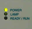
When the instrument drops offline, check to see if the lamp is
still on. If the lamp is off (see picture), the software is not
the problem and the instrument has dropped offline because of a
reset. These type of instrument resets are usually caused by RF
noise being introduced to the reset line of the CPU. If the RF
occurs for long enough, the instrument will do a cold boot. The
fault in this case is usually the power supply but the main
board has been suspected in some cases.
|
|
Relates
to: 325 and 335
Escalation:
Yes (CSB-2004-05-05)
Solution:
Check the age of the D2 Lamp and replace if old. If the
D2 lamp is OK, do the beam alignment test to determine if the
optics module is the problem
|
 |
|
High noise is most often caused by an old D2 lamp. But, in some
cases the optics module can be miss-aligned by extreme shocks
during shipping, causing the lamp intensity to be low. In that
case, replacing the lamp will not solve the problem and the
optics module will have to be replaced. Do the beam alignment
test to check the optics module. If the optics module and lamp
look OK, check the black grounding wire that is connected to the
optics module from the metal frame of the circuit board. Check
it makes good contact between the two surfaces. Without this
wire the 325 will not meet it's noise specifications. Also,
check the optics module for places where light could get in,
especially around the area near the Vis lamp. Cover all holes
with dark colored tape and re-test.
|
Instrument
Name and Lamp Hour Settings Invalid
Relates
to: 325 and 335
Escalation:
No
Solution:
Remove the button cell on the main board, bend the positive
pins upwards and reinsert battery
|
 |
|
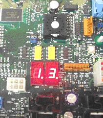
There are some boards that have the backup battery inserted
incorrectly which can bend the positive terminals in the holder.
The battery will not be connected properly and some parts of the
memory may be erased. The factory is aware of the possible fault
and each board is checked, but some detectors may have slipped
through the system prior to June 04. To solve the problem,
remove the battery and bend the positive terminals of the holder
upwards (see picture), then reinsert the battery. Use LCVerify
or PolyVerify to reset the instrument name and lamp hour
settings. To obtain the software, see the
downloads
section of the Downloads page or the CD that was shipped with
the instrument.
|
|
Relates
to: 325 only
Escalation:
Yes (All beam balance escalations)
Solution:
Load 1.07 or 1.08 firmware
|
 |
|
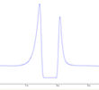
Version 1.07 (and higher) firmware takes the highest of the two
signals (sample or reference) when determining the contents of
the gain table. Version 1.05 firmware only used the reference
path to calculate the gain table, so if the sample beam was
higher than the reference, the gain would be incorrectly set.
The most common symptom is dips on both sides of the peak (see
picture). Changing to 1.07 or later firmware will fix the
problem.
|
|
Relates
to: 325 only
Escalation:
Yes (CSB-2004-06-09)
Solution:
Perform the 0%T calibration and if problem persists do the
Wavescan test to determine if the optics module is the
problem
|
 |
|
The problem is caused by the cross talk and dark current values
being higher than the sample value. When the corrections are
taken away from the sample value it leaves a log of a negative
number (for Abs conversion) which is impossible. The software
then outputs invalid data until the sample values are positive
again. The next generation of firmware (2.x) will avoid this,
but if the 0%T calibration is performed with current firmware,
the problem will disappear. This is because the dark current and
cross talk values will be corrected. Note: If the 0%T
calibration is performed using a white piece of paper the
problem will remain because the white color will fluoresce in UV
light. Always use a black piece of paper when blocking the
sample beam.
|
Peak
Heights Reduced when the Vis Lamp is Turned On
Relates
to: 325 only
Escalation:
No
Solution:
Only use the UV lamp when monitoring UV wavelengths
(<380 nm) and only the
Vis
lamp when monitoring visible wavelengths (>380nm)
|
 |
|
When the UV and Vis lamps are both on, the peak heights in the
chromatogram appear smaller, compared to when only the UV lamp
is on. The effect is caused by the Vis lamp introducing stray
light into the monochromator which is then read as UV light.
When the detector sees more light, the transmission amount seems
higher (less absorbance), so all peaks in the chromatogram
appear smaller (see picture, red trace). This effect can not be
reduced or eliminated and is part of the 325 design, therefore
it is best to use only one lamp at a time. See service bulletin
LCS200407 for
more information.
|
|
Relates
to: 210 and related pumps
Escalation:
Yes
(CSB-2005-11-12,
CSB-2006-03-14, CSB-2006-03-17, CSB-2006-03-8)
Solution:
update the LC Galaxie Drivers with the latest version
|
|
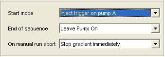 |
| The
pump driver (ver. 1.13.2.1) was changed in Galaxie 1.9 due to
customer demand. The current pump driver (1.13.2.1) does not
stop during a manual stop command. When a user stops the current
run, the pump keeps going until the end of its gradient/run
length. While the pump finishes its run, Galaxie goes into a
Post-Run state and prevents the user from starting a new run. For
further information see Service Bulletin
DSS-2006-04
|
|
Relates
to: PS 325* (V2 firmware and above) and PS 335
Escalation:
No
Solution:
turn the thumb wheel to 14 and press the reset button. Put the
thumb wheel back to 0
|
 |
|
Once a 325/335 Detector has been installed with a fixed IP
address (as recommended for a Galaxie installation) it becomes
very difficult to communicate with this detector on another
system if the fixed IP address is not known. |
Split
Peaks in Extended Range (4 x 0.15 Flow Cells)
Relates
to: 325 and 335
Escalation:
No
Solution:
Increase the flow rate, inject less or use 9x1 cell
|
 |
|
When using the 4x0.15 cell in extended range, low flow rates
(less than 20ml/min) can cause the peaks to look split. This is
because the sample will not be distributed evenly between the
sample and reference paths when the absorbance enters the blend
region (0.8 to 1.2 Abs). This will cause a dip in the output and
make the peak look split. The solution is to increase the flow
rate until the split peak disappears. The 4x0.15 cell has a
minimum recommended flow rate of 80ml/min. It can be used at
lower flows, but it was not designed to do so. A 9x1 cell might
be a better option if low flows are required.
|
PS
210 pump "Flow Error" Message at max flow
Relates
to: 210
Escalation:
No
Solution:
Check the pump refill rate. If the refill rate is
set to high, the pump can not successfully complete a full
stroke cycle in the allocated time causing it to give the error
message “Flow Error”. Reduce the pump refill time to 125 ms
(default setting), by going into the setup menu of the pump on
the front panel.
|
|
|
When running a 10ml SS wash pump head, increasing the flow rate
above 9.2 ml/min causes a pump error message stating "Flow
Error". The pump keeps going, but the flow rate is no longer
accurate. Other issues relating to the fill time:
- Bubbles in the low pressure area of the pump
- Viscosity of the mobile phase
- Ripple noise pattern in the baseline (due to gas in
mobile phase)
|
|
Relates
to: 325 and 335
Escalation:
No
Solution:
Change the Ready In: sync to “disabled”.
|
|
| If a 325 or 335 detector
is configured with the "Enable Ready In" feature
enabled, the detector will be waiting for a "Ready In"
signal, before getting into the "Ready state". You can
either try and create the "Ready In" signal it is
waiting for, or you can open up LCVerify and disable this
function. The latter is probably a bit more reliable.
To do this:
- Open up LCVerify or PolyVerify and connect to the detector
in question. Open the "Diagnostics" by holding
CTRL, SHIFT and F10. Select the "Diagnostic" tab
and "Main" sub-tab.

- If "Enable Ready In" is enabled. Disable this,
click "Set" and reboot the detector. If you leave
the setting to “Enabled”, then the detector will wait
for a signal from a 3rd party piece of hardware.
- the detector will now get into the ready state. However,
don't forget to also disable this in the Galaxie
Configuration Manager before starting another run.
|